Difference between revisions of "UART Console"
CelesteBlue (talk | contribs) |
|||
| (13 intermediate revisions by 4 users not shown) | |||
| Line 1: | Line 1: | ||
| − | The UART0 is a debugging console. The logic level is 1.8V. | + | == UART0 == |
| + | |||
| + | The UART0 is a debugging console used by ARM, cMep and Syscon. The logic level is 1.8V. | ||
| + | |||
| + | === PSTV UART0 location === | ||
| − | |||
[[File:Pstv_uart0.png]] | [[File:Pstv_uart0.png]] | ||
| − | == UART | + | === OLED PS Vita UART0 location === |
| + | |||
| + | [[File:vita-1000-uart.png|600px]] | ||
| + | |||
| + | There are two ways of using UART0: | ||
| + | * First way is to solder directly to the testpads near the PMIC (yellow and cyan points). | ||
| + | |||
| + | * Second way is through the multi-connector or the testpads above it (blue and red points). To use the multi-connector points though, you need either to tell Syscon to select [[Kermit]] UART (procedure currently unknown) or manually flip the switch (green point to 1.8V). | ||
| + | |||
| + | The switch is controlled by a [http://www.ti.com/lit/ds/symlink/ts3a5018.pdf TS3A5018] chip and the RTS gate is a [http://toshiba.semicon-storage.com/ap-en/product/logic/one-gate-logic/detail.TC7WG126FK.html TC7WG126FK] chip. | ||
| + | |||
| + | == UART1 == | ||
| + | |||
| + | The UART1 is a debugging console used by DevKit PS Vita models. | ||
| + | |||
| + | UART1 is pre-initialized by SKBL. | ||
| + | |||
| + | === DevKit PS Vita UART1 location === | ||
| + | |||
| + | Unknown but guessed to be sent to GCP board (Communication Processor). Communication Processor sends received UART1 data over mini-USB which can be seen on PC in the Console Output for PS Vita program. Communication Processor seems to manage input/output from sdio (mini-USB) at regular intervals. | ||
| + | |||
| + | == UART5 == | ||
| + | |||
| + | The UART5 is a debugging console used for the 3G modem on PS Vita models that have it. | ||
| + | |||
| + | === OLED PS Vita UART5 location === | ||
| + | |||
| + | It is on the PCI-E connector pins 8,10,12,14 is RFR, CTS, TX, RX. | ||
| + | * On 3G PS Vita units, you can solder to the PCI-E connectors or install yifan lu's PSVSD board. | ||
| + | * On Wifi PS Vita units, you need to fill in the 88ohm termination resistors (or just short the pads) and some way to enable it (not known yet). | ||
| + | |||
| + | == UART initialization/deinitialization code == | ||
| + | |||
<source lang="c"> | <source lang="c"> | ||
| − | + | scePervasiveUartClkGateEnableForDriver(port); // Turn on clock | |
| − | + | scePervasiveUartResetDisableForDriver(port); // Put out of reset | |
| + | sceKernelUartInitForKernel(port); | ||
/* | /* | ||
| − | * Use UART | + | * Use UART port (read/write) |
* ... | * ... | ||
*/ | */ | ||
| − | + | scePervasiveUartResetEnableForDriver(port); // Put to reset | |
| − | + | scePervasiveUartClkGateDisableForDriver(port); // Turn off clock | |
</source> | </source> | ||
Revision as of 16:29, 10 January 2022
UART0
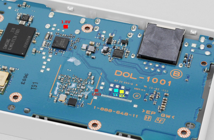
The UART0 is a debugging console used by ARM, cMep and Syscon. The logic level is 1.8V.
PSTV UART0 location
OLED PS Vita UART0 location
There are two ways of using UART0:
- First way is to solder directly to the testpads near the PMIC (yellow and cyan points).
- Second way is through the multi-connector or the testpads above it (blue and red points). To use the multi-connector points though, you need either to tell Syscon to select Kermit UART (procedure currently unknown) or manually flip the switch (green point to 1.8V).
The switch is controlled by a TS3A5018 chip and the RTS gate is a TC7WG126FK chip.
UART1
The UART1 is a debugging console used by DevKit PS Vita models.
UART1 is pre-initialized by SKBL.
DevKit PS Vita UART1 location
Unknown but guessed to be sent to GCP board (Communication Processor). Communication Processor sends received UART1 data over mini-USB which can be seen on PC in the Console Output for PS Vita program. Communication Processor seems to manage input/output from sdio (mini-USB) at regular intervals.
UART5
The UART5 is a debugging console used for the 3G modem on PS Vita models that have it.
OLED PS Vita UART5 location
It is on the PCI-E connector pins 8,10,12,14 is RFR, CTS, TX, RX.
- On 3G PS Vita units, you can solder to the PCI-E connectors or install yifan lu's PSVSD board.
- On Wifi PS Vita units, you need to fill in the 88ohm termination resistors (or just short the pads) and some way to enable it (not known yet).
UART initialization/deinitialization code
scePervasiveUartClkGateEnableForDriver(port); // Turn on clock
scePervasiveUartResetDisableForDriver(port); // Put out of reset
sceKernelUartInitForKernel(port);
/*
 * Use UART port (read/write)
 * ...
 */
scePervasiveUartResetEnableForDriver(port); // Put to reset
scePervasiveUartClkGateDisableForDriver(port); // Turn off clock
