UART Console: Difference between revisions
(→UART0) |
(Add UART3 ane UART6) |
||
| (One intermediate revision by one other user not shown) | |||
| Line 13: | Line 13: | ||
There are two ways of using UART0: | There are two ways of using UART0: | ||
* First way is to solder directly to the testpads near the PMIC (yellow and cyan points). | * First way is to solder directly to the testpads near the PMIC (yellow and cyan points). | ||
* Second way is through the multi-connector or the testpads above it (blue and red points). To use the multi-connector points though, you need either to tell Syscon to select [[Kermit]] UART by calling <code>[[SceSyscon#sceSysconSetMultiCnPortForDriver]](1);</code>, or to manually flip the switch (green point to 1.8V). | |||
* Second way is through the multi-connector or the testpads above it (blue and red points). To use the multi-connector points though, | |||
The switch is controlled by a [http://www.ti.com/lit/ds/symlink/ts3a5018.pdf TS3A5018] chip and the RTS gate is a [http://toshiba.semicon-storage.com/ap-en/product/logic/one-gate-logic/detail.TC7WG126FK.html TC7WG126FK] chip. | The switch is controlled by a [http://www.ti.com/lit/ds/symlink/ts3a5018.pdf TS3A5018] chip and the RTS gate is a [http://toshiba.semicon-storage.com/ap-en/product/logic/one-gate-logic/detail.TC7WG126FK.html TC7WG126FK] chip. | ||
| Line 20: | Line 19: | ||
== UART1 == | == UART1 == | ||
UART1 is a debugging console used by DevKit PS Vita models. | |||
UART1 is pre-initialized by SKBL. | UART1 is pre-initialized by [[SKBL]]. | ||
=== DevKit PS Vita UART1 location === | === DevKit PS Vita UART1 location === | ||
Unknown but guessed to be sent to GCP board (Communication Processor). Communication Processor sends received UART1 data over mini-USB which can be seen on PC in the Console Output for PS Vita program. Communication Processor seems to manage input/output from sdio (mini-USB) at regular intervals. | Unknown but guessed to be sent to GCP board (Communication Processor). Communication Processor sends received UART1 data over mini-USB which can be seen on PC in the Console Output for PS Vita program. Communication Processor seems to manage input/output from sdio (mini-USB) at regular intervals. | ||
== UART3 == | |||
Unknown, but initialized by [[SceSysmem]] for STDOUT in 0.920 firmware if DIP switch 0xC4 is set. | |||
== UART5 == | == UART5 == | ||
| Line 37: | Line 40: | ||
* On 3G PS Vita units, you can solder to the PCI-E connectors or install yifan lu's PSVSD board. | * On 3G PS Vita units, you can solder to the PCI-E connectors or install yifan lu's PSVSD board. | ||
* On Wifi PS Vita units, you need to fill in the 88ohm termination resistors (or just short the pads) and some way to enable it (not known yet). | * On Wifi PS Vita units, you need to fill in the 88ohm termination resistors (or just short the pads) and some way to enable it (not known yet). | ||
== UART6 == | |||
Probably wired to [[Ernie | Syscon]]. | |||
The [[SceDeci4pSCTtyp]] module relays all traffic from this port to Host PC. (It does not allow ''writing'' to this port, though) | |||
== UART initialization/deinitialization code == | == UART initialization/deinitialization code == | ||
Latest revision as of 21:56, 19 July 2024
UART0
The UART0 is a debugging console used by ARM, cMep and Syscon. The logic level is 1.8V.
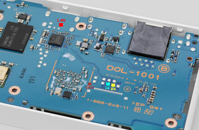
PSTV UART0 location
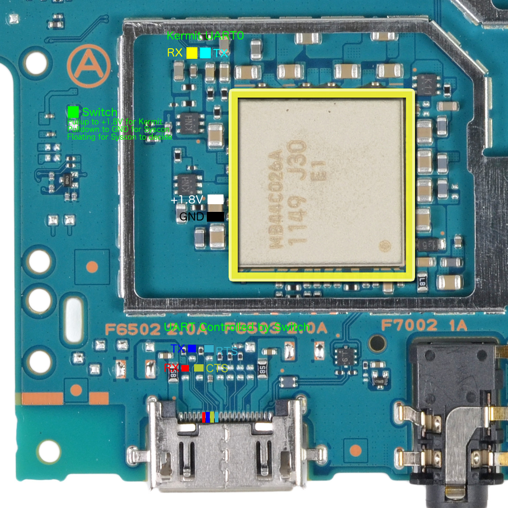
OLED PS Vita UART0 location
There are two ways of using UART0:
- First way is to solder directly to the testpads near the PMIC (yellow and cyan points).
- Second way is through the multi-connector or the testpads above it (blue and red points). To use the multi-connector points though, you need either to tell Syscon to select Kermit UART by calling
SceSyscon#sceSysconSetMultiCnPortForDriver(1);, or to manually flip the switch (green point to 1.8V).
The switch is controlled by a TS3A5018 chip and the RTS gate is a TC7WG126FK chip.
UART1
UART1 is a debugging console used by DevKit PS Vita models.
UART1 is pre-initialized by SKBL.
DevKit PS Vita UART1 location
Unknown but guessed to be sent to GCP board (Communication Processor). Communication Processor sends received UART1 data over mini-USB which can be seen on PC in the Console Output for PS Vita program. Communication Processor seems to manage input/output from sdio (mini-USB) at regular intervals.
UART3
Unknown, but initialized by SceSysmem for STDOUT in 0.920 firmware if DIP switch 0xC4 is set.
UART5
The UART5 is a debugging console used for the 3G modem on PS Vita models that have it.
OLED PS Vita UART5 location
It is on the PCI-E connector pins 8,10,12,14 is RFR, CTS, TX, RX.
- On 3G PS Vita units, you can solder to the PCI-E connectors or install yifan lu's PSVSD board.
- On Wifi PS Vita units, you need to fill in the 88ohm termination resistors (or just short the pads) and some way to enable it (not known yet).
UART6
Probably wired to Syscon.
The SceDeci4pSCTtyp module relays all traffic from this port to Host PC. (It does not allow writing to this port, though)
UART initialization/deinitialization code
scePervasiveUartClkGateEnableForDriver(port); // Turn on clock
scePervasiveUartResetDisableForDriver(port); // Put out of reset
sceKernelUartInitForKernel(port);
/*
 * Use UART port (read/write)
 * ...
 */
scePervasiveUartResetEnableForDriver(port); // Put to reset
scePervasiveUartClkGateDisableForDriver(port); // Turn off clock
