UART Console: Difference between revisions
Jump to navigation
Jump to search
CelesteBlue (talk | contribs) No edit summary Tags: mobile edit mobile web edit |
|||
| Line 1: | Line 1: | ||
== UART0 == | |||
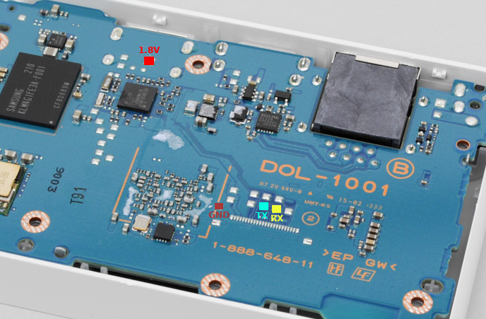
The UART0 is a debugging console. The logic level is 1.8V. | The UART0 is a debugging console. The logic level is 1.8V. | ||
== | === PSTV UART0 location === | ||
[[File:Pstv_uart0.png]] | [[File:Pstv_uart0.png]] | ||
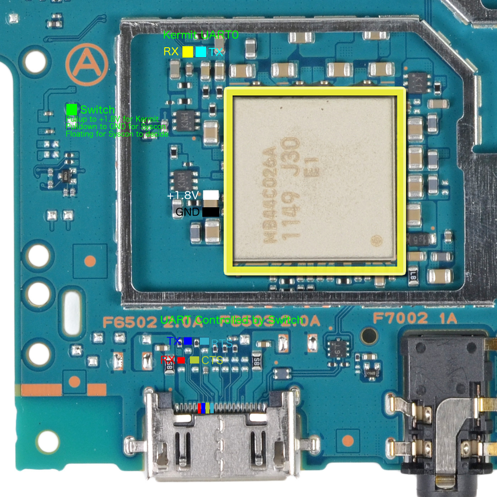
== OLED | === OLED PSVita UART0 location === | ||
[[File:vita-1000-uart.png|600px]] | [[File:vita-1000-uart.png|600px]] | ||
There are two ways of using UART0: | |||
* First way is to solder directly to the testpads near the PMIC (yellow and cyan points). | |||
* Second way is through the multi-connector or the testpads above it (blue and red points). To use the multi-connector points though, you need either to tell the syscon to select the Kermit UART (procedure currently unknown) or manually flip the switch (green point to 1.8V). | |||
The switch is controlled by a [http://www.ti.com/lit/ds/symlink/ts3a5018.pdf TS3A5018] chip and the RTS gate is a [http://toshiba.semicon-storage.com/ap-en/product/logic/one-gate-logic/detail.TC7WG126FK.html TC7WG126FK] chip. | The switch is controlled by a [http://www.ti.com/lit/ds/symlink/ts3a5018.pdf TS3A5018] chip and the RTS gate is a [http://toshiba.semicon-storage.com/ap-en/product/logic/one-gate-logic/detail.TC7WG126FK.html TC7WG126FK] chip. | ||
== OLED | == UART5 == | ||
=== OLED PSVita UART5 location === | |||
It is on the PCI-E connector pins 8,10,12,14 is RFR, CTS, TX, RX. | |||
* On 3G PSVita units, you can solder to the PCI-E connectors or install yifan's PSVSD. | |||
* On Wifi PSVita units, you need to fill in the 88ohm termination resistors (or just short the pads) and some way to enable it (not known yet). | |||
== UART Initialization Code == | |||
<source lang="c"> | <source lang="c"> | ||
kscePervasiveUartClockEnable(uart_bus); // Turn on clock | kscePervasiveUartClockEnable(uart_bus); // Turn on clock | ||
Revision as of 23:31, 13 August 2018
UART0
The UART0 is a debugging console. The logic level is 1.8V.
PSTV UART0 location
OLED PSVita UART0 location
There are two ways of using UART0:
- First way is to solder directly to the testpads near the PMIC (yellow and cyan points).
- Second way is through the multi-connector or the testpads above it (blue and red points). To use the multi-connector points though, you need either to tell the syscon to select the Kermit UART (procedure currently unknown) or manually flip the switch (green point to 1.8V).
The switch is controlled by a TS3A5018 chip and the RTS gate is a TC7WG126FK chip.
UART5
OLED PSVita UART5 location
It is on the PCI-E connector pins 8,10,12,14 is RFR, CTS, TX, RX.
- On 3G PSVita units, you can solder to the PCI-E connectors or install yifan's PSVSD.
- On Wifi PSVita units, you need to fill in the 88ohm termination resistors (or just short the pads) and some way to enable it (not known yet).
UART Initialization Code
kscePervasiveUartClockEnable(uart_bus); // Turn on clock
kscePervasiveUartResetDisable(uart_bus); // Out of reset
ksceUartInit(uart_bus);
/*
 * Use UART bus
 * ...
 */
kscePervasiveUartResetEnable(uart_bus); // Put to reset
kscePervasiveUartClockDisable(uart_bus); // Turn off clock
